How do I express logical connectives with Nand?
Really struggling to understand how to express all the connectives as Nand. I understand that p ^ q would be the opposite of p nand q, but I get stuck when trying to express p -> q and p v q in terms of nand. I'm hoping somebody can inform me on the process.
$\endgroup$ 43 Answers
$\begingroup$(1)
$$p\Rightarrow q$$ can be expressed as $$\overline p \lor q$$ or
$$\overline{\overline{\overline p \lor q}}=\overline{p\land \overline q}.$$
That is,
(2)
$$p\lor q$$
can be expressed as
$$\overline {\overline{p\lor q}}=\overline{\overline p \land \overline q}.$$
The diagram can be created now:
You can do the following: As the truth table of $NAND$ is:
$$\begin{matrix} {A}&{B}&{A\otimes B}\\ {\underline{0}}&{\underline{0}}&{\underline{1}}\\ {0}&{1}&{1}\\ {1}&{0}&{1}\\ {\underline{1}}&{\underline{1}}&{\underline{0}} \end{matrix}$$
Notice that the lines with $0,0$ and $1,1$ are almost a $NOT$, then you can plug one wire in both $A$ and $B$, this will give you:
$$\begin{matrix} {A}&{A}&{A\otimes B}\\ {\underline{0}}&{\underline{0}}&{\underline{1}}\\ {\underline{1}}&{\underline{1}}&{\underline{0}} \end{matrix}$$
This is the schematic:
$\quad \quad \quad \quad \quad \quad \quad \quad \quad \quad \quad \quad \quad $
Now connecting the new $NOT$ gate in the output of our $NAND$, we will have the $AND$ gate:
$$\begin{matrix} {A}&{B}&{A\otimes B}&{¬(A\otimes B)=A\wedge B}\\ {0}&{0}&{1}&{0}\\ {0}&{1}&{1}&{0}\\ {1}&{0}&{1}&{0}\\ {1}&{1}&{0}&{1} \end{matrix}$$
The schematic is:
$\quad \quad \quad \quad \quad \quad \quad \quad \quad \quad \quad $
Now we need to obtain the $OR$ gate, this can be achieved by negating $A$ and $B$. This reflects the inputs of the truth table, as you can see below. Also, notice that $(¬A\otimes ¬B)\neq ¬(A\otimes B) $:
$$\begin{matrix} {A}&{B}&{¬A}&{¬B}&{(¬A\otimes ¬B)= A\vee B}\\ {0}&{0}&{1}&{1}&{0}\\ {0}&{1}&{1}&{0}&{1}\\ {1}&{0}&{0}&{1}&{1}\\ {1}&{1}&{0}&{0}&{1} \end{matrix}$$
The schematic is:
$\quad \quad \quad \quad \quad \quad \quad \quad \quad \quad \quad $
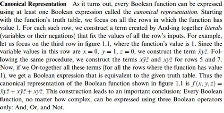
Wait! Here comes the crescendo: Having these $3$ logical connectives allow you to express any logical circuit you want with a tool called cannonical representation. From Nisan/Shocken's: The Elements of Computing Systems:
If you want to know more, this is known as Canonical Normal Form. There is also another similar way to do it that is called Disjunctive Normal Form. Notice that an expression taken with these methods will probably not be optimized, that is, with the fewer quantity of components possible. To minimize the expressions/circuits, you can use the axioms of boolean algebra or Karnaugh/Veitch's Maps which are a little more visual and sometimes people prefer this because of this setting.
Hahahahahaha, How beautiful! Is it not?
$\endgroup$ $\begingroup$Any logical statement can be expressed as a combination of AND, OR and NOT. This is self-evident when you use a truth table to derive the expression of a Boolean function in terms of its inputs... A simple approach is to express these 3 elementary logical operators (AND, OR, NOT) in terms of NAND. And then replace whatever expression with their logical equivalents expressed in terms of NAND.
For instance,
NOT(a) = NAND(a,a) as NAND(a, a) = NOT(AND(a,a)) = NOT(a)
AND(a,b) = NAND(NAND(a,b), NAND(a,b))
OR(a,b) = NOT(AND(NOT(a), NOT(b)))
// To express OR(A,B) exclusively in terms of NAND, just replace NOT and AND by their expressions in terms of NAND.
//Now that you have AND , OR and NOT expressed in terms of NAND, you can express any other boolean expression in terms of NAND by replacing AND, OR and NOT in terms of their equivalent expression of NAND
$\endgroup$